

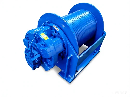

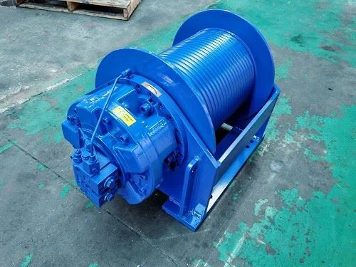

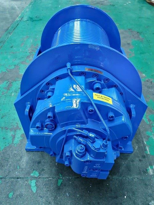

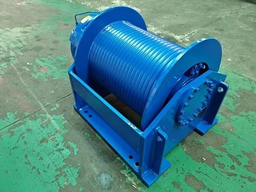


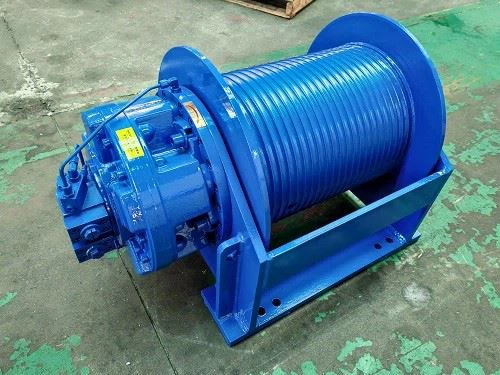

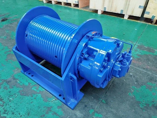
The GW4 hydraulic winch is designed for heavy-duty pulling and lifting applications in construction, crane systems, mining, petroleum, marine and other industrial equipment.
The GW4-65-58-20-ZP configuration provides a first-layer pulling force of 65 kN, a rope speed of 11 m/min, a wire rope capacity of 58 m and a recommended rope diameter of 20 mm.
The winch uses a hydraulic drive system and can be configured according to the required pulling force, rope capacity, operating speed, mounting arrangement and working conditions.
The GW4 6.5 ton hydraulic winch is positioned as a medium-capacity hydraulic traction and lifting solution for equipment that requires controlled pulling force and reliable rope handling.
Construction and engineering machinery
Truck-mounted cranes and lifting equipment
Mining and material-handling equipment
Petroleum and geological equipment
Marine and deck machinery
Railway and specialized service equipment
Construction Machinery: Pulling and lifting materials and equipment in construction applications.
Crane Equipment: Hydraulic winch systems for selected lifting and pulling operations.
Mining: Pulling and material-handling applications in demanding industrial environments.
Petroleum and Geological Equipment: Suitable for selected pulling, handling and positioning applications.
Marine Equipment: Selected deck machinery and shipboard pulling applications.
Railway and Specialized Equipment: Hydraulic pulling and handling applications for maintenance and service equipment.
The GW4-65-58-20-ZP configuration provides a first-layer pulling force of 65 kN for medium-capacity lifting and pulling applications.
The hydraulic drive system allows the winch to be integrated with hydraulic equipment used on construction, crane and industrial machinery.
The specified configuration provides a wire rope capacity of 58 m with a recommended rope diameter of 20 mm.
The integrated transmission arrangement provides a compact hydraulic winch package for equipment where installation space needs to be considered.
Winch configuration can be selected according to pulling force, rope diameter, rope capacity, hydraulic motor, installation dimensions and operating requirements.
The following specifications are provided for the GW4-65-58-20-ZP configuration.
| Specification | GW4 |
|---|---|
| Model | GW4 |
| Load Capacity | 5-6 ton class |
| Rope Capacity | 20-150 m |
| Working Speed | 20-50 m/min |
| Hydraulic Motor | GN3 |
| Warranty | 12 months |
| Model | First Layer | Total Displacement (ml/r) | Working Pressure Difference (MPa) | Rope Diameter (mm) | Wire Rope Capacity (m) | Layers | |
|---|---|---|---|---|---|---|---|
| Pull (kN) | Rope Speed (m/min) | ||||||
| GW4-65-58-20-ZP | 65 | 11 | 6104 | 18 | 20 | 58 | 2 |


The listed configuration provides 65 kN first-layer pulling force for medium-capacity hydraulic pulling and lifting applications.

Hydraulic motor and transmission components are arranged as an integrated winch drive system.

Rope, hydraulic motor and mounting configuration can be selected according to the target machine and operating requirements.
The GW4-65-58-20-ZP hydraulic winch is a 65 kN first-layer pulling configuration designed for medium-capacity industrial pulling and lifting applications. Its 20 mm rope specification, 58 m rope capacity and 11 m/min first-layer rope speed provide a defined configuration for equipment requiring controlled hydraulic winch operation.
For equipment integration, the final winch selection should be confirmed according to load, rope arrangement, hydraulic pressure and flow, mounting dimensions and operating conditions.
Hydraulic winch selection should be based on the actual operating requirements rather than nominal tonnage alone.
Required pulling force
Required rope speed
Wire rope diameter and capacity
Hydraulic pressure and flow
Mounting dimensions
Duty cycle and operating environment
Regular inspection helps maintain safe and reliable winch operation. Maintenance intervals should follow the manufacturer's instructions and the actual working conditions.
Inspect the hydraulic hoses, fittings and connections for leakage or damage.
Check hydraulic fluid condition and maintain the recommended fluid level.
Inspect the wire rope for wear, corrosion, kinking or deformation.
Check the drum and mounting structure for abnormal wear or damage.
Inspect the brake and control system according to the applicable maintenance requirements.
Payment: 30% deposit and 70% before shipment. T/T is generally accepted, with other payment terms subject to negotiation.
Delivery: Lead time depends on product specification, order quantity and production schedule.
Service: 24-hour online support and technical service are available.
The specified configuration provides a first-layer pulling force of 65 kN.
The GW4-65 configuration provides approximately 65 kN of first-layer pulling force, which corresponds to the commonly used 6.5 ton class in product descriptions.
The listed GW4-65-58-20-ZP configuration has a wire rope capacity of 58 m with a recommended rope diameter of 20 mm.
The specified first-layer rope speed is 11 m/min.
The GW4 series overview lists GN3 as the hydraulic motor. The detailed configuration should be confirmed according to the final hydraulic system and motor specification.
Yes. Configuration can be discussed according to pulling force, rope diameter, rope capacity, hydraulic motor, mounting dimensions and application requirements.
Maintenance should include inspection of the hydraulic system, wire rope, drum, brake, mounting structure and lubrication system according to the manufacturer's maintenance instructions.
The minimum order quantity is 1 set.


